


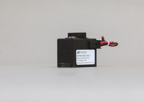
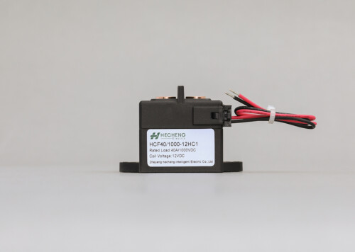
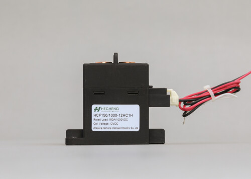
600A High voltage DC relay 800Vdc 1000Vdc 1500Vdc.
High Voltage DC Relay Contactors 600A 800Vdc 1500Vdc
Description
| HC | F | 600 | □ / | 1000 | – 12 | H | C | 1 | □ | □ | – () | ||||||
|---|---|---|---|---|---|---|---|---|---|---|---|---|---|---|---|---|---|
| HC: Company Code | |||||||||||||||||
| F: Square Series | |||||||||||||||||
| Contact Rating: 600: 600A | |||||||||||||||||
| Derivative Model: Nil: Basic Model | |||||||||||||||||
| Load Voltage 450: 450VDC; 800: 800VDC; 1000: 1000VDC;1500:1500VDC | |||||||||||||||||
| Coil Voltage: 12:12VDC; 24:24VDC; 48:48VDC | |||||||||||||||||
| Main Contact Type H: SPST-NO | |||||||||||||||||
| Coil Input Terminal:C:Connector; | |||||||||||||||||
| Load Input Terminal:1:External thread | |||||||||||||||||
| Auxiliary Contact: H: SPST-NO | |||||||||||||||||
| Mounting Nil:Vertical Mounting | |||||||||||||||||
| Special Code:XXX:Customer Special Code;Nil:Standard | |||||||||||||||||
1、Ceramic Seal Structure, Filled In H2 Mixed gas, Resist Contacts Oxidation , Lead To Low Contact Resistance
2、A Group of Normally Open Auxiliary Contacts Built In
3、Ceramic Seal Structure With Magnetic Blow-out Technology, Realize Zero Arc, Assure Use Safety And Reliability
4、High Resistance To Short Circuit
5、Full Compliance With RoHS Requirements
6、UL CUL TUV CE CCC approved
Why Choose Us?
Design to improve short-circuit resistance
Why need to resist the external force when electrified:
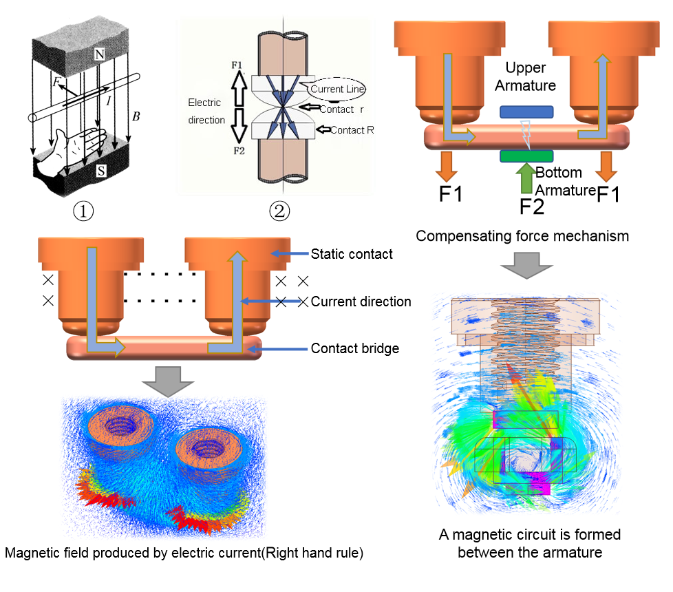
- 1. The ampere force of a energized conductor in a magnetic field (Figure ①):
- According to the left-hand rule, the magnetic field generated when energized will cause the contact bridge to receive a relatively downward force;
- 2. Electric contraction force generated by contact energization (Figure ②):
- The microscopic contact surface is not smooth, and the current line shrinks through the contact surface, which causes an electric repulsion between the contacts to prevent the contacts from closing.
- When a short-circuit current or a large current occurs, the above forces have a huge impact on the contact bridge, and even directly cause the contacts to separate and generate an arc, which affects safety.
How to resist the external force when electrified:
- Principle: Placing an armature fixed relative to the contact bridge at a suitable position above the contact bridge, and the other armature is bound to the contact bridge. The magnetic field generated by the energization magnetizes the two armatures to form a magnetic circuit, and then attracts each other to force the contact bridge upward.
The effect achieved by this design:
- This design overcomes the limited space in the ceramic arc extinguishing cavity, Reasonably achieved the compensating force mechanism, and can be used in contactors above 100A;
- This design can ensure that the contacts are reliably closed and not separated when passing a current of 8kA, which improves the short-circuit resistance of the product.
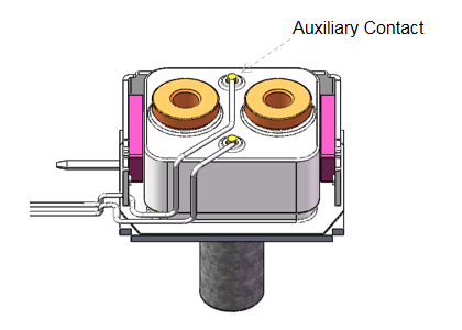
Design Of Square Ceramic Auxiliary Switch
Reasons for setting auxiliary switches :
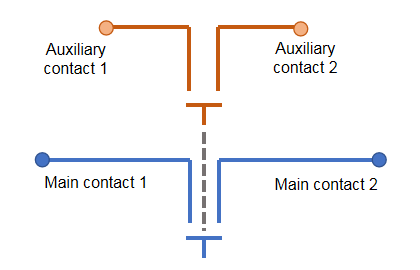
- The auxiliary switch is a monitoring mechanism synchronized with the on-off state of the main contact, which load is small and main function is signal feedback.
- Many applications need to monitor the working status of the contactor at present, such as whether it is in the disconnected state or whether it can be turned on and off normally etc.
Design of auxiliary switch:
- Through some transmission mechanism or signal transmission to reach the auxiliary switch, then gets the feedback of the working status of the main loop.
Difficulties in the design of auxiliary switches:
- Ceramic interior space is limited.
- Ensure the performance of electrical life and temperature rise.
- Special structure design.
Effect of auxiliary switch:
- Overcoming the limited space problem, being applied in products above 100A.
- Accurately and reliably monitor the working status of the main contact, and the parameters and status still meet the requirements.
Other Features
Product application platform:
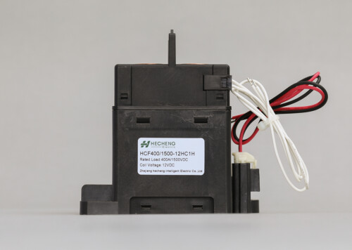
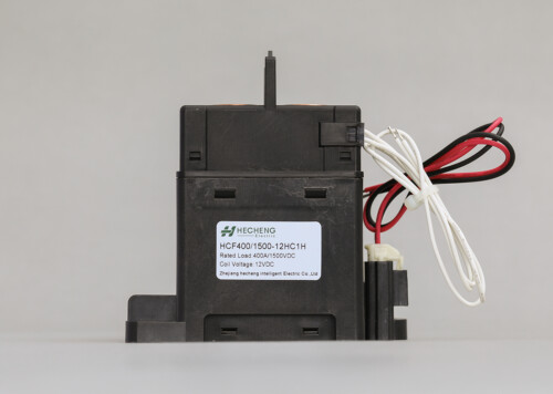
- The design of the entire series of products is based on the 1000V voltage platform requirements.
- 400A series products meet the requirements of 1500V voltage platform, being used in super charging, photovoltaic, energy storage and other application scenarios.
Product Advantages:
- Ceramic sealing structure.
- The cavity is filled with hydrogen gas mixture to prevent oxidation of the contacts. And the gas leakage rate is less than or equal to 6.0*e-9Pa.m3/s, and long service life to meet the vehicle quality assurance requirements.
- Non-polar arc extinguishing design, whish is suitable for the two-way current scenario of the loop, and uses ceramic seals to achieve zero flashover, ensuring safety and reliability.
-
HCF600.stp
Size: 6.09 MB
Type: stp
Reviews
There are no reviews yet.